Setting Filters
Creating a Filter
The rectangular surface filter is the default tool to apply a filter in a time/frequency area of the spectrum. This filter allows to globally increase or decrease the amplitude of the spectral components. Once this surface is created, its features – dimensions, intensity, contour – can be modified.
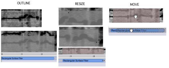
To draw a surface filter on the sonogram, select the red/blue square tool and click and drag the mouse on the sonogram. A grey rectangle appears.
To modify the filter's duration or frequency area, hover the mouse over the desired edge of the filter until a double triangle appears. Then, click and drag the mouse.
To move the filter, click and drag it.
As you noticed, the filter is also represented in the Processing Sequencer, below the sonogram. This sequencer allows to edit this filter independently from any manipulations in the sonogram.
By default, filters are on Gain mode. This means that the user can choose freely the amount of gain to be added or substracted to the spectral components, from 116 to -116 dB. To set the intensity gain or loss
Scroll the mouse up or down. The square will get blue or red, depending whether the intensity if increased of decreased. We will set filters to -116 dB, which actually amounts to "shut down", or reject the spectral components. |

 |
|
The dB value of the filter is applied globally to the whole area of the spectrum. If the intensity of the area is increased beyond the limits of the system, be careful not to choose values which could lead to clipping[1] the signal.
Basic Edition Commands
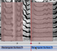 | Standard manipulations, such as cut copy-paste or delete, can be applied to filters in the sonogram window, or in the processing sequencer.
|
If you don't select another location, the new filter will be superimposed on the original filter, and won't be visible. Click and drag it with the mouse. | 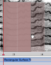 |
The intensity of several filters can be modified globally. mouse drag and Select the filters with a To change their intensity,
|
Ctrlclick on one of the filters and scroll the mouse up of down. Note that the intensity of both filters will be reset according to the value of the filter that was clicked on.

Parameters Edition
The filter's characteristics –area, intensity and contour – can be edited via the inspector window. Select the filter with a click, double click in the desired prompt, type a value and press | 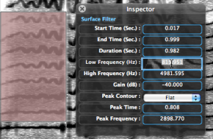 |
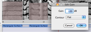
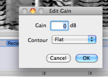
The gain of the filter can also be modified via the treatment's internal editor from the processing sequencer:
|  |
Pre-Listen
The resulting sound can be pre-listened to before processing the treatments. Click on the corresponding command of the player: ![]()
This command can be used as a play/stop command. You can also stop the play with the space bar.
- Audio Clipping
Clipping is a form of waveform distortion that occurs when an amplifier is overdriven. The signal is amplified at which point the signal simply "cuts" or "clips" at the maximum capacity of the amplifier. The extra signal is simply cut off, resulting in a sine wave becoming a distorted square-wave-type waveform
In digital signal processing, the signal is restricted by the range of a chosen representation. For example, in a 16-bit system, 32767 is the largest positive value that can be represented. If the amplitude of the signal is doubled, sample values of, for instance, 32000 should become 64000, but instead they are truncated to the maximum, 32767.
Source : http://en.wikipedia.org/wiki/Clipping_(audio)

