Frequency Modulation Synthesis with FM-2
Tutorial FM-2
Name | Description | Default value |
|---|---|---|
amp | Maximum Amplitude. Linear from >0.0 to 1000 or in dB from 0 to -∞ (see Tutorial Getting Started 02 - Amplitude and Internal Editor for more details) | -6.0 |
f0 | NOT IN SERVICE | |
freq | Carrier frequency | 500.0 |
fmod | Modulating frequency | 100.0 |
imax | Maximum index (of freq modulation) [flt] | 5 |
imin | Minimum index (of freq modulation) [flt] | 0 |
aenv | Amplitude Envelope [GEN] | Instance: GEN07 |
ienv | Envelope for the index [GEN] | Instance: GEN07 |
The FM-1 Class realizes a simple Frequency Modulation Synthesis with the following controls:
- The main amplitude,
- The frequency of the carrier,
- The frequency of the modulator,
- The amplitude envelope by means of a GEN routine,
- The index envelope by means of a GEN routine,
- The range between (imax & imin) of the index envelope.
There are few little differences between the FM-1 and FM-2 classes.
FM-1 | FM-2 |
|---|---|
The Carrier is the generating frequency (f0) multiplied by the factor n1. | The Carrier is directly given. |
The Modulator is the generating frequency (f0) multiplied by the factor n2. | The Modulator is directly given. |
The amplitude and index envelope are initialized by a GEN05. | The amplitude and index envelope are initialized by a GEN07. |
The slot f0 is not in service. |
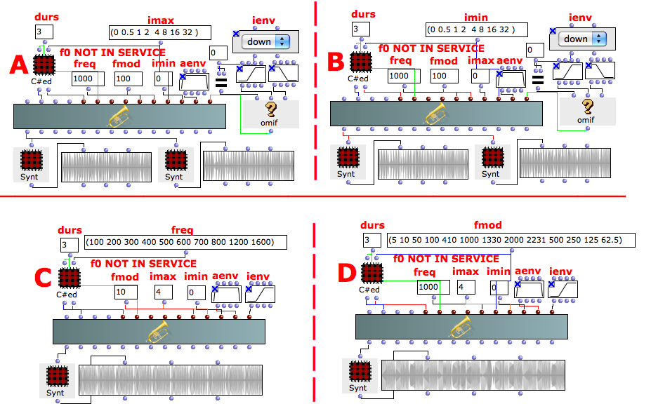
These examples give the same results as the Tutorial FM-1 entering the data in a different way.
The example A & B show the meaning of the FM index: the number of the components of the side-band frequencies increase with the rising of the index.
The example C focuses on the carrier frequency with a steady sideband width (10 Hz). The sound begins rough and ends with a nice vibrato for the sake of the ratio between the modulating and the carrier frequency. At the beginning the sidebands are 10% away from the carrier (10/100 = 0.1). At the end they are 0.625% away (10/1600).
The example D focuses on the ratio between the modulating and the carrier frequency.
- M/C > 0.1 -> vibrato,
- M/C = integer or 1/2^n -> harmonic spectra,
- M/C = floating -> inharmonic spectra.
If imax>imin the BPF given as envelope is read forwards as usual (example A) but if imax<imin the BPF is read backwards (example B).
Try to evaluate the object with both envelopes each with a different synt.
For the red patch C#ed and Synt see Appendix A
Inside the Class
instr 1
idur = p3
idurosc = 1/idur
iamp = (p4 > 0.0 ? (p4*0.001*0dbfs) : (ampdbfs (p4)))
if0 = p5 ; unused here
icar = p6 ; carrier
imod = p7 ; modulating
imax = p8
imin = p9
imindev = imin*imod
imaxdev = imax*imod
ivardev = imaxdev-imindev
iaenv = p10
ienv = p11
icarfun = 1
imodfun = 2
ieps = 0.01 ; short fadeout (avoid clicks in exp envelopes)
ken poscil iamp, idurosc, iaenv ; amplitude envelope
k1 linseg 1, idur-ieps, 1, ieps, 0 ; avoid clicks
kenv = ken * k1
ki poscil ivardev, idurosc, ienv ; dynamic modulator
kind = imindev + ki
amod poscil kind, imod, imodfun
asound poscil kenv, icar+amod, icarfun ; carrier
out asound
endin

- OMChroma User Manual
- System Configuration and Installation
- Getting started
- Managing GEN function and sound files
- Predefined Classes
- Additive Synthesis
- Buzz Synthesis
- Frequency Modulation Synthesis
- Frequency Modulation Synthesis with FM-1
- Frequency Modulation Synthesis with FM-2
- Formant Wave-Function Synthesis (FOF)
- Granular Formant Wave Function (FOG)
- Karplus-Strong
- Random Amplitude Modulation
- Sampler
- Subtractive Synthesis
- Wave Shaping Synthesis
- Hybrid Models
- User-fun
- Creating a new Class
- Multichannel processing
- Appendix A - Common Red Patches
